
First You Make a Hull…
A father and son build a wooden boat
Story and photos by Brian Graham
My son decided he would build a wooden motorboat, lusting after the classic vintage wooden power boats. And it was a project we could undertake together. His research led him to settle on a more modest project: a small outboard powered wooden boat, finally selecting the Zip design by Glen-L. He purchased the plans about a year ago, and we perused them for several months before starting.
The design calls for hardwood (mahogany) frames, keel, chine, sheer and battens, with 3/4” marine plywood transom and stem, and the hull of 1/4” marine plywood. We substituted sapele for mahogany, and obtained marine plywood from Windsor Plywood. They stock it in fir but were happy to order tropical veneer marine plywood on request.
The plans came with full scale stem and half frame and transom drawings. Unfortunately, the drawings were distorted: the centre lines of the frames were not perpendicular to the floor line of the frames, and the error varied from positive to negative angles. Rather than “fudge” a compromise line, I chose to draw the frames from the information and measurements provided on scaled drawings, risking missing out on optimizations they had from experience of building boats and applied to the full-scale drawings.
These drawings were used to cut full size templates on a CNC from 1/4” MDF. In February, we started to cut wood: shape outlines were marked on the sapele, rough cut on a bandsaw, then flush trimmed to the templates with a router, with some inside corners chiseled square where needed.
Building frames
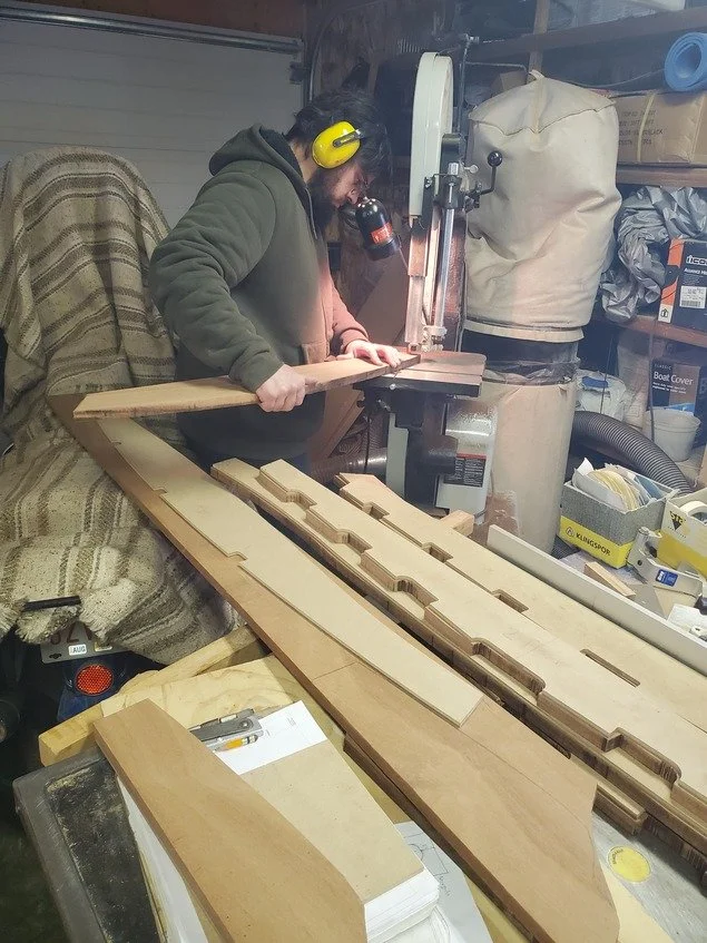
Each frame consisted of a top, bottom, and two side pieces, and these were glued in the lapped corners with filled epoxy. (Epoxy adhesive is not gap filling without the addition of fillers such as Silica.) The transom is 3/4” marine plywood on the outside, and is laminated inside with sapele around the perimeter and marine plywood at the motor mount. The stem is two thicknesses of 3/4” marine plywood, again glued with epoxy. All the joints also have silicone bronze screws.
Figure 1 Cutting Frame Pieces
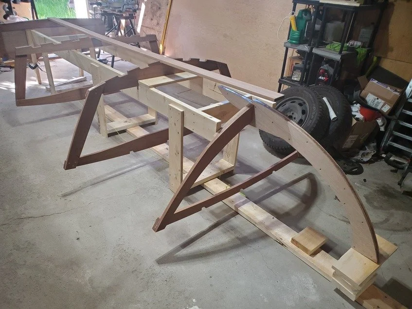
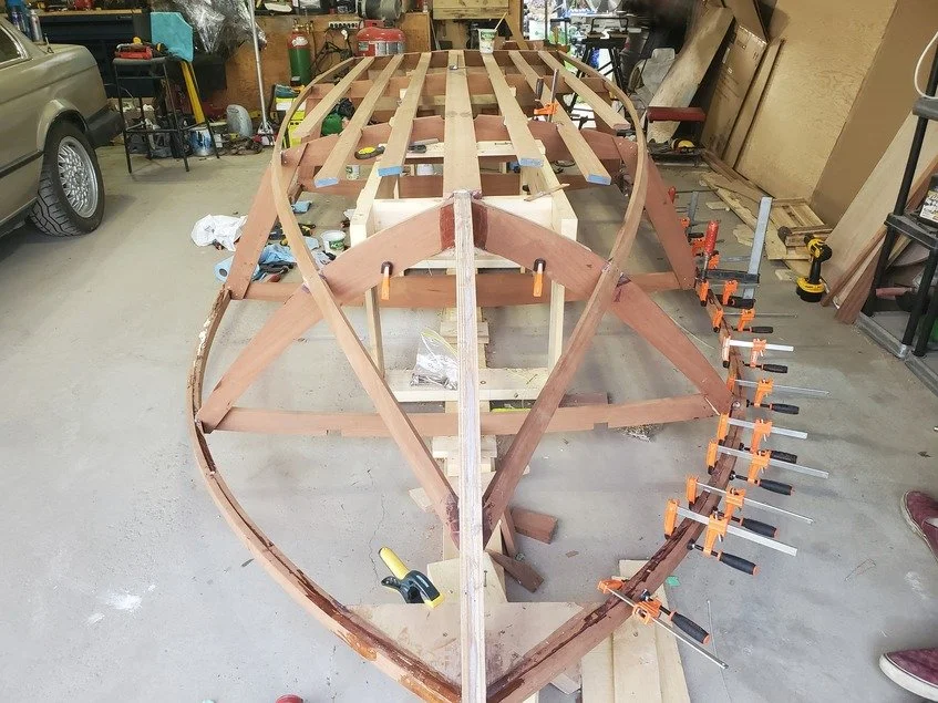
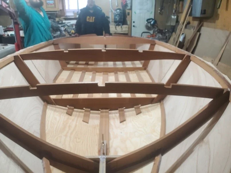
The next step was to construct a “building frame”, the equivalent of a strongback used when building a canoe. The frame must be rigid, level, and preferably straight, and well secured so it won’t move. A 2x6 is anchored to the floor, then the frame parts attached, with two 2x6 timbers level and parallel at a comfortable height for working on. Notches in the 2x6s locate the frames, and the aft end of the 2x6s are cut to 12° for the desired slope of the transom. The frame is screwed together, as the upper 2x6s will go through the middle of the boat frames.
Mounting the frames is guided by notches and one cross piece of the building frame. Note that the boat will sit upside down on the frame. The transom leans against the sloped end of the building frame, and is aligned so the bottom (which is at the top) is level with the nearest frame. Much effort went into ensuring the frames were aligned and perpendicular to the centre line.
The keel, made from 1x4 sapele, fits in notches in each frame, and also joins the aft part of the stem. We discovered that our stem was misshapen, not mating properly with the keep and the forward most frame, so we redesigned it based on the full-scale drawing, and cut a new one.
Fitting the chine
With all frames solidly attached, and the transom, keel and stem in place, work began on fitting the chine. (The chine is the line where the sides of the boat meet the bottom. This design has a “hard chine” as opposed to a rounded chine.) 1x2 sapele fits into notches cut in the corners of the frames. The notches are individually fitted for the angle of the curve of the chine where it meets each frame. It will be planed to mate with the plywood hull at a later stage.
Our next and biggest error occurred when installing the chine. Instead of starting at the stem and working aft (as per the instructions), we started at the transom and worked forward, leaving the difficult part of joining to the stem until the end. Much later, we observed that this likely resulted in less curvature of the chine near the stem, and some added difficulty in mating the hull plywood. Another problem was that the plans did not give any precise information about where the chine should meet the stem.
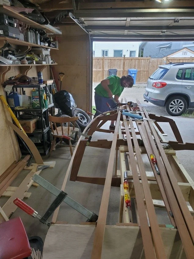
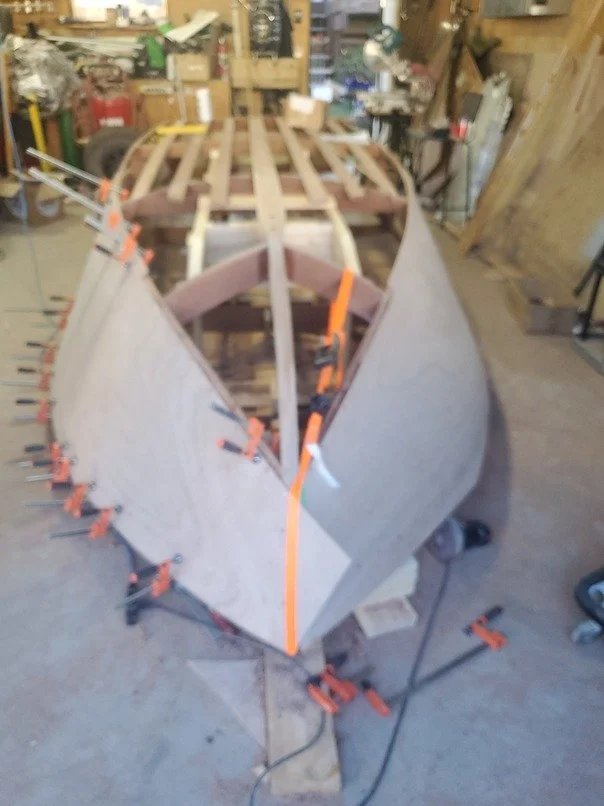
Next was installation of the sheer. (The sheer is where the side of the hull meets the deck.) Because it has an even tighter curve than the chine, it is laminated from 2 pieces of 5/8” x 1 1/2” sapele. This time, having read the instructions more carefully, we started from the stem and worked aft. The relatively tight working space (one side of a double garage) made bending this in place quite a challenge, and we used tie-down straps to help, along with many clamps.
After getting the first pieces secured (epoxied and screwed to the stem, frames, and transom), attaching the second layer was a bit easier, as we could clamp it to the already-in-place strip, ensuring a good glue-up.
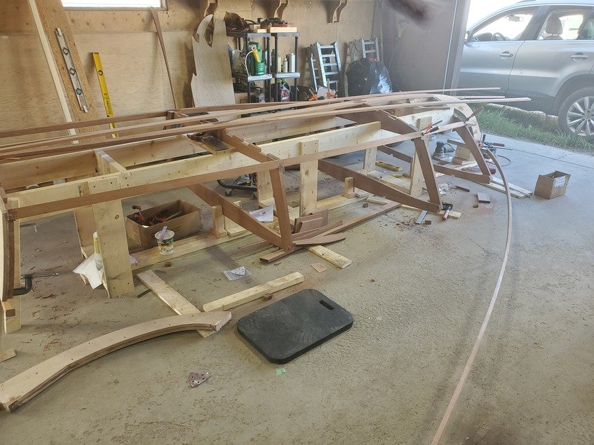
Slats along the bottom of the hull were added, in the precut recesses in the frame bottoms. We bumped up from 4 1x2 slats to 6 1x3 slats for added strength of the hull. A lot of hand planing, belt and random orbit sanding created surfaces on all the chines, sheers and slats that will mate with the hull plywood.
More fitting challenges
The boat is 14’-4” long, so our 8’ plywood sheets would have to be joined. Rather than scarf joining and working with 16’ sheets, we chose to butt join the 8’ sheets, with a 12” wide backer of the same plywood over the joins. We started with the forward sides of the hull. The join between the side and bottom plywood is a butt joint forward, then becomes a lap joint where the angle between the side and bottom becomes greater.
Fitting the bottom started at the stem. The plywood is bevelled along the keel, so both sides meet in the centre of the keel. We crept up to a fit to the butt joint to the side plywood. As the plywood curved down towards the stem, the straight edge along the keel moved further past the centre line, to be trimmed off later.
Because of the force required to bend the plywood, we used a combination of clamps and tie-down straps, and 1/4” plywood washers on the screws to give more surface bearing. We tried to ensure that any gaps were completely filled with epoxy.
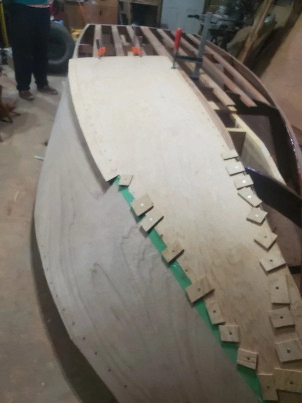
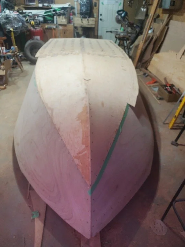
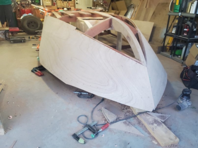
Plywood overlaps are trimmed off and will be sanded flush. These last stages were being done in November in an uninsulated and minimally heated garage. We were thankful the warmer weather lasted as long as it did this year. An oscillating tool with saw blade attached proved very handy in trimming the excess plywood.
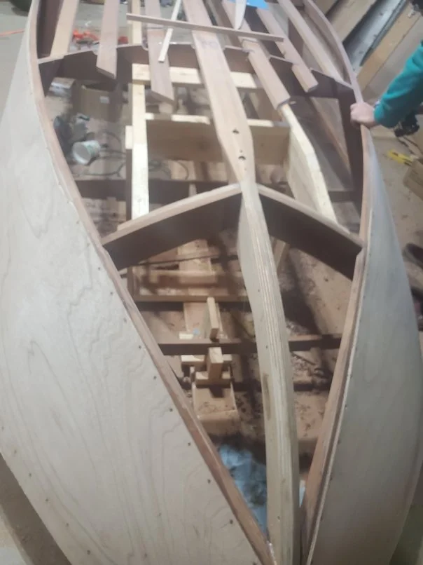
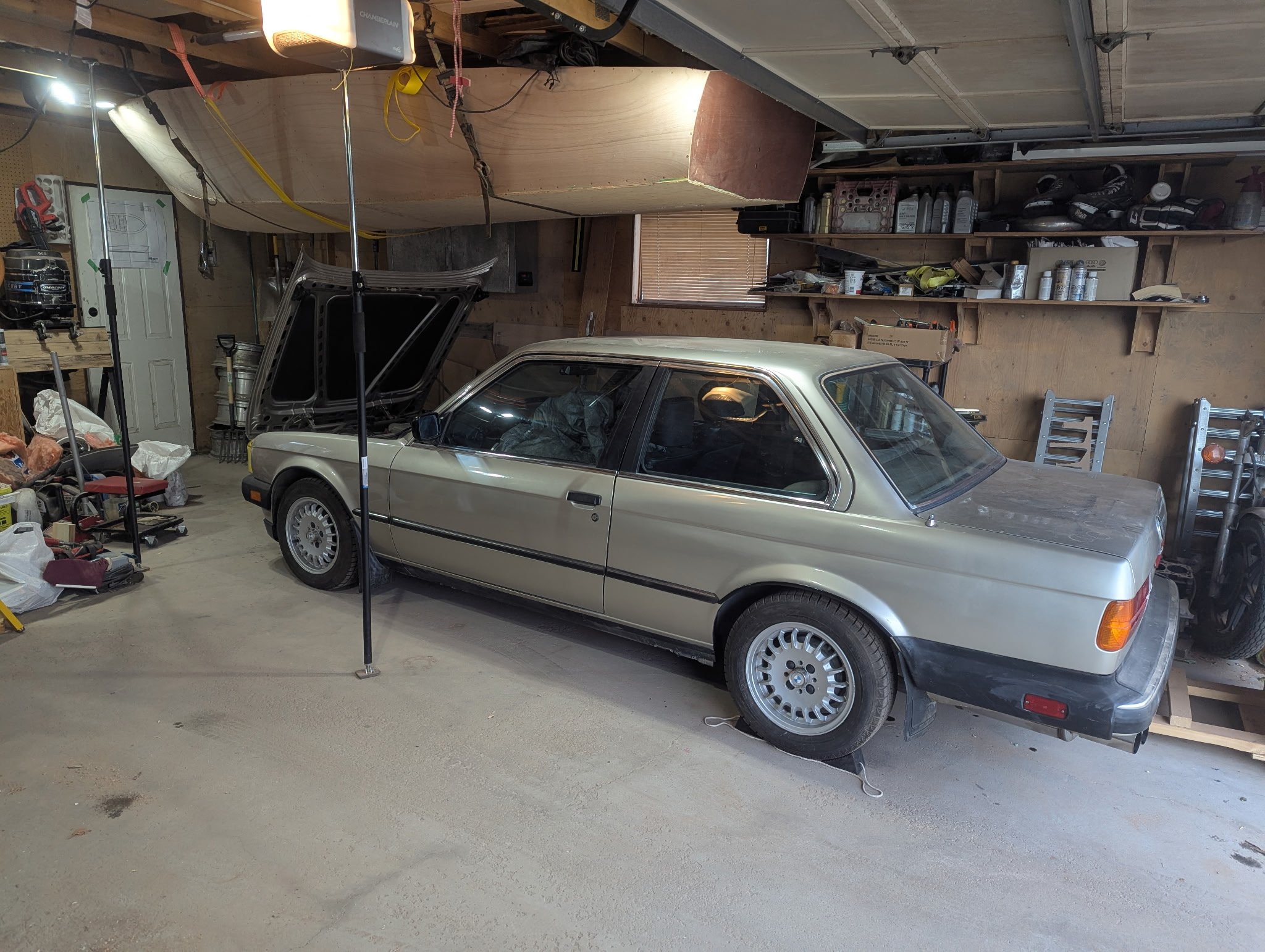
Taking the boat off the building form was a milestone, and allowed us to see the boat interior for the first time. Side plywood was trimmed to the sheer, before the boat hull was hoisted to the underside of the garage trusses, to wait for spring. And leaving a parking space below.
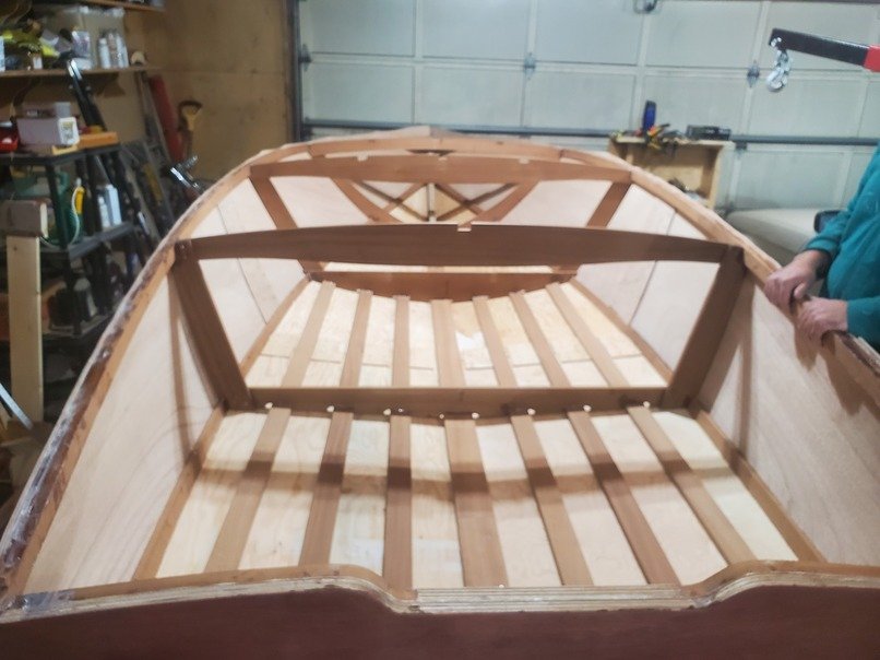
The plywood hull is complete. We may be halfway along in the overall project. Our next steps will be installing the deck, cockpit fittings and seating, fibreglassing the exterior, and all the other parts to make it a functioning boat.